Lecture 1 - Digital Abstraction
This course: how do we physically implement computation?
- Bridging the gap between computer programs → physical devices
An introduction to the digital world! 0. Devices, materials, atoms
- Digital design: combinational and sequential circuits
- Computer architecture: processors, caches, pipelining
- Computer systems: operating systems, virtual memory, I/O
- 💡 How have we been able to design new generations of processors, chips, ... so quickly?
- Abstractions! There are well-defined abstractions between each of these layers that allow for parallel progress across all these fronts.
computer programs
---virtual machines---
computer sysems
---instruction set + memory---
computer architecture
---digital circuits---
digital design
---bits, logic gates---
devices, materials, atoms
(^ the horizontal separators are the abstractions.)
Engineering abstractions
Good abstractions let us reason about behavior while shielding us from the details of the implementation.
- Abstractions allow us to have the different layers of computer systems evolve independently!
- ⚠️ Anything bad about these abstractions?
- These interfaces (e.g., instruction set) live very long, s.t. interfaces designed with a particular technology in mind may become suboptimal when the technology changes.
- e.g., processors used in PCs are x86, which were designed in Intel in the 70s -- and we are still saddled with a lot of the design choices made back then!
Course outline
- Module 1: Digital design
- Combinational and sequential circuits
- Module 2: Computer architecture
- Simple and pipelined processors
- Caches and the memory hierarchy
- Module 3: Computer systems
- Operating system and virtual memory
- Parallelism and synchronization
CPUs!
Course focus: Systems with general-purpose processors (aka. CPUs - central processing unit).
- ❓ Why not GPUs, TPUs, network cards, etc.?
- General-purpose processors (CPUs) are the basic building block of computer systems.
- CPUs are the most sophisticated digital systems that exist today - understanding them will help you design all kinds of hardware (GPUs, TPUs, etc.)!
- By the end of the term, you will have designed a processor from scratch!
- Will be building toward a complete processor across each of the labs
The digital abstraction
Building digital systems in an analog world.
Analog vs. digital systems
2 ways of encoding information:
- Analog systems: represent and process information using continuous signals
- e.g., voltage, current, temperature, pressures, ...
- Every possible value of the signal is valid!
- Digital systems: represent and process information using discrete symbols
- Typically binary symbols (bits)
- Encoded using ranges of a physical quantity (e.g., voltage)
- 💡 Digital systems tolerate noise!
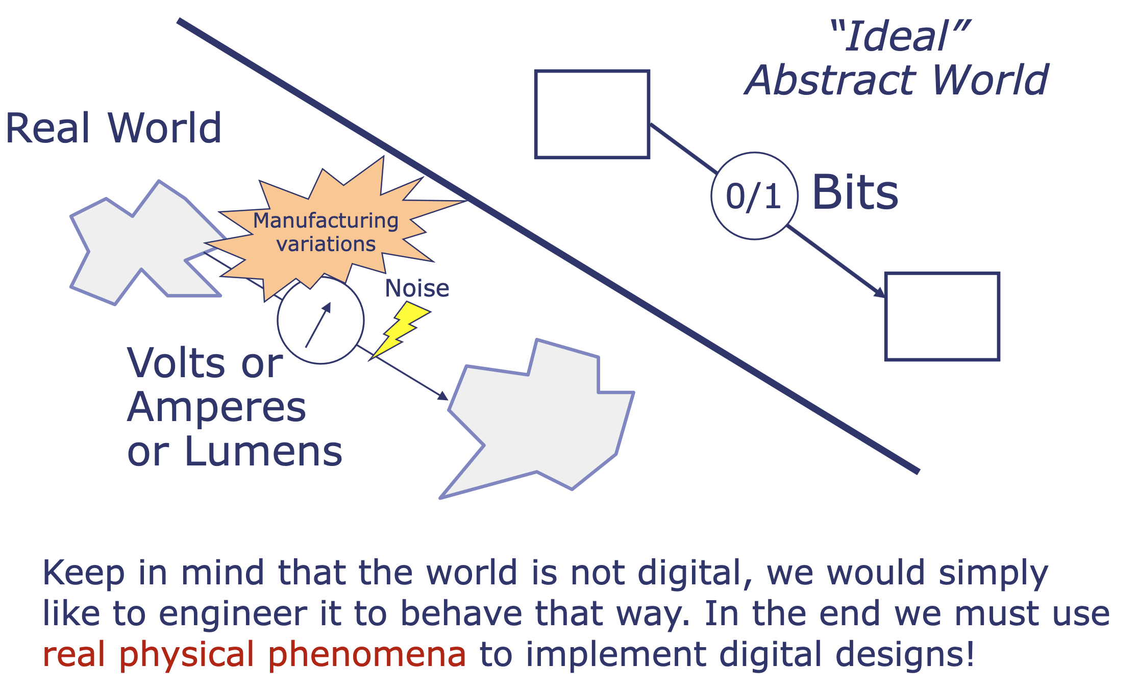
We live in an analog world, but we want to encode information using digital systems. Need to figure out how to do this!
Why don't we use analog systems?
- Sensitive to noise!
- The world is noisy! Also...
- Manufacturing variations
- Components degrade over time
- So our goal is to take the analog, noisy world and extract from it clean, digital signal:
Using voltages "digitally"
Key idea: Encode two symbols, "0" and "1" (1 bit)
- Attempt 1: Threshold , where interpreted as "0" and interpreted as "1"
- ⚠️ Issue: it's really hard to distinguish between values that are very close to the threshold!
- Attempt 2: 2 thresholds!
- interpreted as "0", "undefined," interpreted as "1"
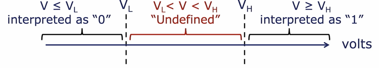
- 💡 We engineer things so that we avoid the undefined region.
- What if we have noise that might push us into the undefined region? Noise margins!
- interpreted as "0", "undefined," interpreted as "1"
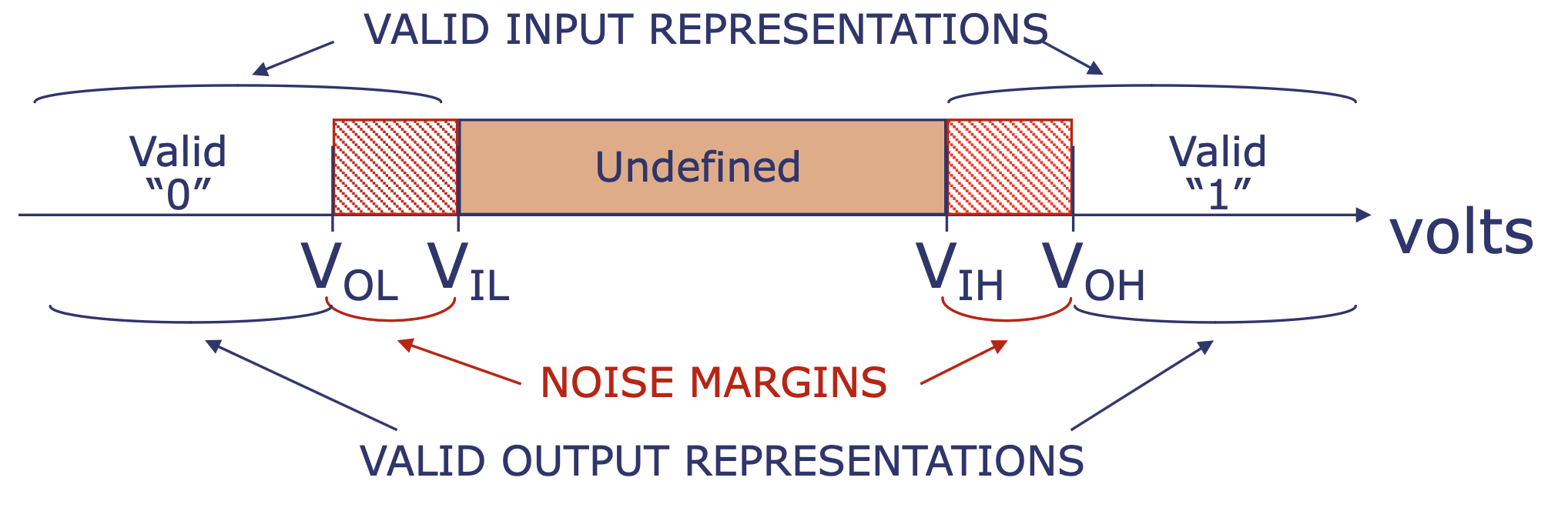
Noise margins
Imagine two logic gates connected by a wire:
- Output = logic gate sending the signal
- Input = logic gate down the line receiving the signal
We implement different specifications (to add noise margins) for output/input because wires aren't perfect: as signal travels from the sender (output) to the receiver (input), it degrades.
- Electrical interference, resistance, temperature changes... add noise to the voltage
- ⚠️ If the sender and receiver had the same standard for what constitutes a "1" or a "0", even tiny noise in voltage on the wire would cause the receiver to misread the signal.
Solution: noise margins!
- Digital output: "0" if , "1" if
- Digital input: "0" if , "1" if
Digital systems fight noise! They actively remove noise.
- Analog systems: noise accumulates
- Digital systems: noise is canceled at each stage
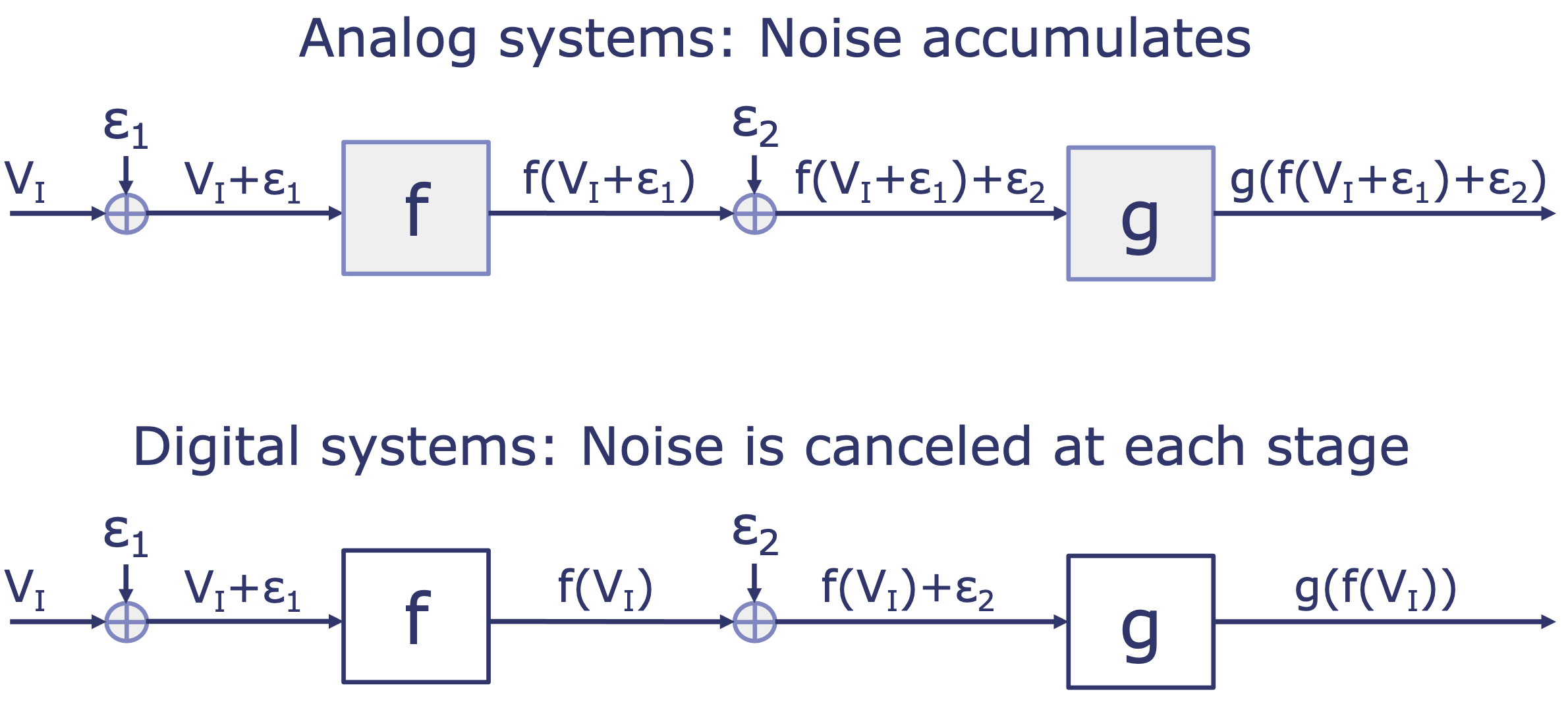
- 💡 Intuitively, canceling noise requires active components, i.e., components that inject energy into the system.
- Intuition: Imagine an output gate sends a perfect 5.0V signal (a logical "1") → as it travels down the wire, electrical resistance and noise degrade it → by the time it reaches the next gate, it has dropped to 4.2V.
- If we want to "cancel" this noise and pass a perfect 5.0V to the next stage - where does that missing 0.8V come from? [Need to inject energy into the systems!]
- 📍 We need active components (transistors) that are connected to a power supply!
- ❓ How does the active gate know to rebuild the signal as a clean "0" or "1"? → decision-making rule = VTC!
- Intuition: Imagine an output gate sends a perfect 5.0V signal (a logical "1") → as it travels down the wire, electrical resistance and noise degrade it → by the time it reaches the next gate, it has dropped to 4.2V.
Interlude: What is a logic gate?
A logic gate is the fundamental building block of all digital computation: its sole purpose is to take one or more binary inputs (0/1) and apply a simple mathematical rule (AND, OR, ...) to produce a single binary output.
- 💡 A logic gate is essentially a tiny, automated decision-maker!
- AND gate: Only outputs "1" if both Input A and Input B are "1"
- OR gate: Outputs "1" if either Input A or Input B are "1"
- NOT gate: Flips the input.
- 🔑 By wiring many (billions!) of logic gates together in specific patterns, we build circuits that add numbers together, store memory, execute the instructions of a processor... :0
What is a logic gate physically composed of?
A logic gate is a specific arrangement of transistors wired together:
- Materials: semiconductor materials (usually silicon) → silicon is treated (doped) with other elements so its electrical properties can be manipulated.
- Transistors: ^ using that silicon, we build transistors!
- Transistor = a microscopic electrical switch (like a light switch that is flipped by electricity itself) → if you apply a small voltage to the transistor's "gate" terminal, it allows a larger current to flow through its other terminals.
- 🔑 To build a logic gate, you wire a few transistors together.
- e.g., building a physical AND gate:
imagine two transistors wired in series along a single wire carrying voltage- If you only apply voltage to the first transistor, it acts as a closed switch, but the electricity stops at the second transistor: output = 0
- "closed" - think of a transistor like a drawbridge (not like a door)!
- Open switch: drawbridge is up → the physical wire is broken/disconnected. Electricity stops flowing!
- Closed switch: drawbridge is down → physical wire is connected end-to-end. Electricity flows!
- "closed" - think of a transistor like a drawbridge (not like a door)!
- ^ same logic if you only apply voltage to the second transistor! output = 0
- If you apply voltage to both transistors simultaneously, the circuit is completed, electricity flows all the way through, and the wire outputs a high voltage: output = 1
- If you only apply voltage to the first transistor, it acts as a closed switch, but the electricity stops at the second transistor: output = 0
- e.g., building a physical AND gate:
Voltage transfer characteristic (VTC)
A VTC is a graph showing output voltage (y-axis) versus input voltage (x-axis) for a specific gate.
- In an analog system, the VTC is a straight diagonal line:
- If the input goes up by 10%, the output goes up by 10%
- Noise accumulates!
- In a digital system, the VTC is nonlinear: it is flat at the extremes and steep in the middle.
- Example VTC: below is the VTC for a buffer logic gate!
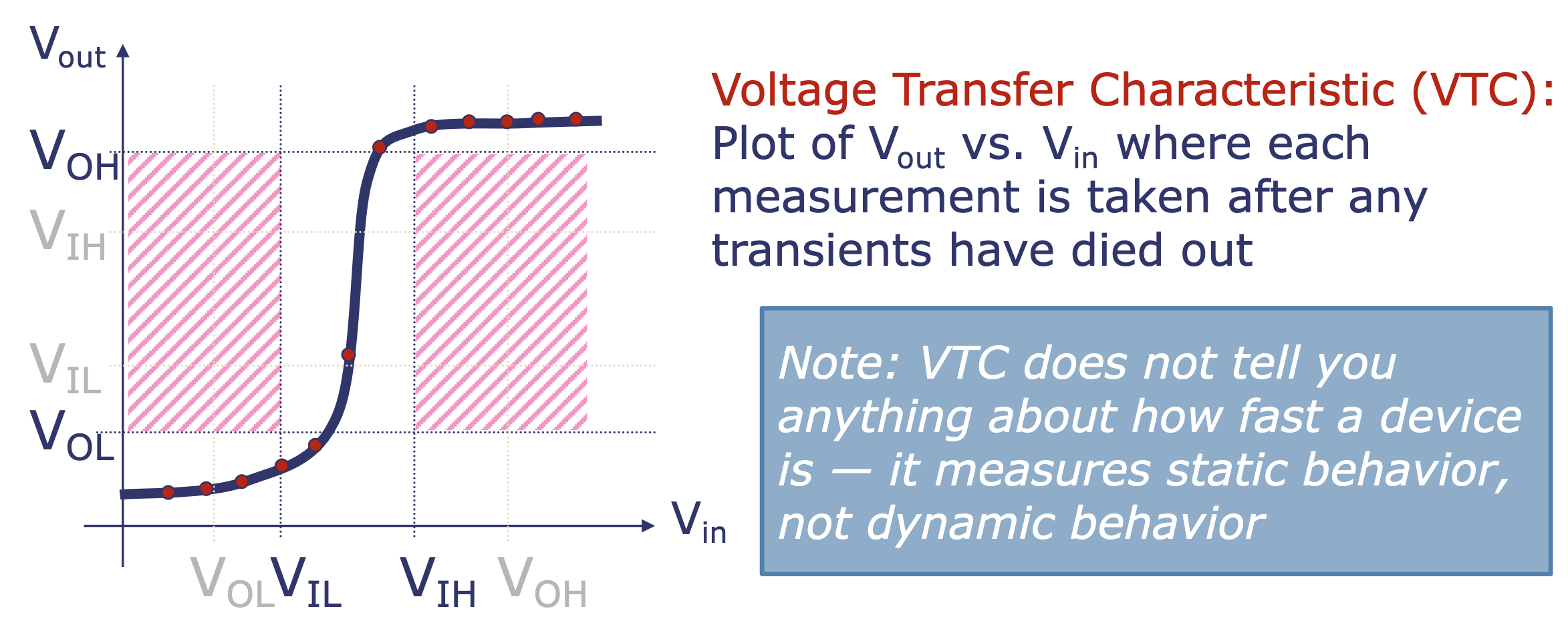
- ⚠️ VTC must avoid the shaded regions ("forbidden zones") which correspond to valid inputs but invalid outputs.
- More details about the VTC:
- Physical mechanism: (physical breakdown of a logic gate)
- Power source (energy in): every active logic gate is permanently connected to a main power supply (aka. , e.g. 5.0V) and ground (0.0V). is like a massive, high-pressure water tower.
- Transistors (valves): inside the logic gate are transistors that act as valves. The input wire () connects to the "handle" of these valves.
- Output (): this is the pipe coming out of the valves.
- 💡 Suppose the buffer receives a "1" input of 4.5V:
- This voltage turns the physical transistor valve fully ON, directly connecting the output pipe to the 5.0V water tower.
- The output floods with exactly 5.0V.
- ^ this causes the largely flat VTC curve between → output does not wiggle so long as the valve remains open ()
- Energy is dissipated through microscopic capacitors that absorb extra charge temporarily and then dissipate it as heat.
- What is a VTC? A VTC is the contract of a specific logic gate - it plots exactly what steady-state output voltage you will get for every possible input voltage
- It is static, not dynamic! The VTC graph assumes you wait for the voltage to settle - it does not show how fast the gate switches.
- Forbidden zones: if the VTC ever enters these zones, the gate is defective!!
- Left forbidden zone: the input is a valid "0" but the gate is outputting an undefined/high voltage (when it should be outputting a low voltage)
- Right forbidden zone: the input is a valid "1" but the gate is outputting an undefined/low voltage (should be outputting a high voltage)
- Middle: (between and )
- The VTC curve can theoretically be anything in the "Undefined" input zone -- the digital contract states that "if you give me a voltage in this middle region, I make zero promises about what I will output"
- This region must have gain > 1!
- , so → so any curve that crosses this region must have climbed a tall vertical height over a relatively shorter horizontal distance →
- Passive components (e.g. resistors) can never have gain > 1 because they can only lose energy → therefore, logic gates must be built using active components (e.g. transistors connected to a power supply).
- 🔖 Gain is a measure of amplification: it describes how much a system multiplies the signal you feed into it. In the context of the VTC curve:
- Physical mechanism: (physical breakdown of a logic gate)
Buffer logic gate
A buffer outputs whatever you input: "0" → "0", "1" → "1"
- Buffers are useless for logic, but essential for physics!
- A piece of wire is a passive component: as signal travels down a long wire across a computer chip, resistance and interference cause the voltage to droop and pick up noise → if you string too many logical operations together, a "1" can eventually degrade into the "Undefined" zone and the computer crashes :"(
- Buffers fix this! When you place a buffer in the middle of a long wire, it receives the degraded signal as its input and then triggers a fresh voltage directly from the power supply to then output a clean signal.
- (In this lecture) - buffers are introduced because they make teaching the concept of a VTC easy (they have a simple VTC plot).
Types of digital circuits
2 main classes:
- Combinational circuits:
- Do not have memory
- Each output is a function of current input values
- e.g., inverter (0→1, 1→0), AND
- Sequential circuits:
- Have memory (state)
- Each output depends on current state + current inputs
Summary
- Digital systems tolerate noise
- Digital encoding
- Valid voltage ranges for representing "0" and "1"
- Undefined range avoids mistaking "0" for "1" and vice versa
- Noise margins require tougher standards for outputs than for inputs
digital inputs → [circuit] → digital outputs